Background information
For AHSS welding in automotive industry one of the technically important products is laser welded blanks (LWB), also known as tailor welded blank (TWB). LWBs are composed of two or more sheets of similar or dissimilar materials, thicknesses and/or coating types welded together, which are formed to fabricate the required three dimensional automotive body parts. Use of LWBs can reduce weight and minimize part cost minimization through better material utilization. Generally, LWBs are made with mild or interstitial free steels; however, in recent years the weight reduction ability of LWBs have been increased by employing high strength steels like high strength low alloy (HSLA) steel and AHSS which also improves the crash performance of the blanks. So, it is known that laser welding is an important process in automotive manufacturing which needs further understanding and research.
Current research at Centre for Advanced Materials Joining focuses broadly on characterization of microstructure and evaluation of properties (hardness, tensile and fatigue) of AHSS and HSLA LWBs. This is because LWBs represent the majority of the automotive laser welding applications. The LWBs are made using a novel 8kW multi-process hybrid welding system and IPG YLS-6000 fiber lasers with robotic arms. LWBs are almost exclusively welded as butt joints. In addition, formability of TWBs have also been explored using Hecker’s limiting dome height (LDH) test set up and compared with numerical simulation of the stretch forming process.
Objectives
- To characterize the microstructure and mechanical properties of the LWBs of various AHSS and HSLA steel
- Fundamental understanding of the softening phenomenon i.e. martensite tempering occurring in the sub-critical heat-affected zone (HAZ) of DP and martensitic steel LWBs
- To study the effectiveness of high speed fiber laser welding in minimizing the HAZ softening in dual-phase steel and assess the subsequent enhancement in properties
- Investigation of the fatigue behaviour of the LWBs as a function of the differences in properties, coating, and/or thicknesses of the AHSS
- To examine the effect of weld line position and geometry on fatigue and forming behaviour of LWBs
Equipment
- High power multi-process laser welding system (with 8 kW fibre laser)
- IPG YLS-6000 fibre laser
- Optical microscope
- Microhardness tester
- JEOL 6460 Scanning electron microscope
- Instron tensile testing machine
- Limiting dome height test machine
- Circular grid marking (etching) system
- Double action MTS 866 metal form press
- FMTI Grid Analyzer (Model 100)
- FE software: Hypermesh, Hyperform and lsdyna
Pictures/figures
(Further details can be found in the Publications section)
Microstructure and hardness
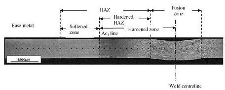
Figure 1 Overview of DP980 steel LWB sheet weldment showing different zones
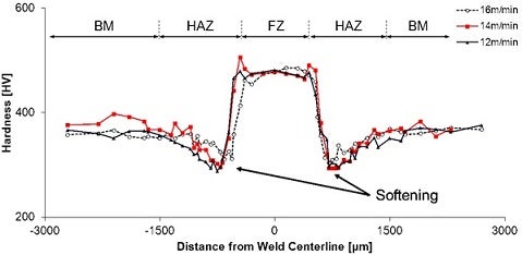
Figure 2 Effect of welding speed on hardness profile across DP980 steel fiber laser welds
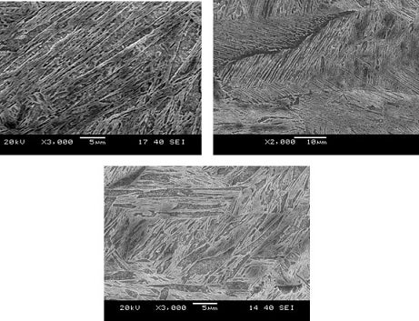
Figure 3 Fusion zone microstructure developed in fiber laser welding of similar and dissimilar combination LWBs of DP980 and HSLA steels
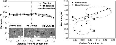
Figure 4 Variation of fusion zone hardness in laser welding with (a) distance from weld centerline and (b) the fusion zone carbon content
Tensile and fatigue testing
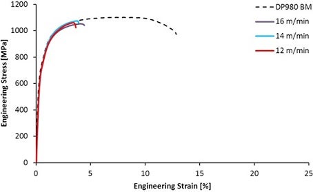
Figure 5 Stress-strain curves of transverse specimens of DP980 steel LWBs prepared by fiber laser welding
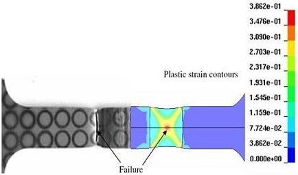
Figure 6 Strain localisation in softened zone observed in both experiment and FE simulation
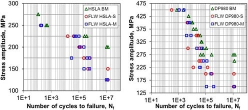
Figure 7 S-N curves of transverse specimens of HSLA and DP980 steel LWBs prepared by fiber laser welding (S: single linear weld, M: multiple linear welds)
Formability
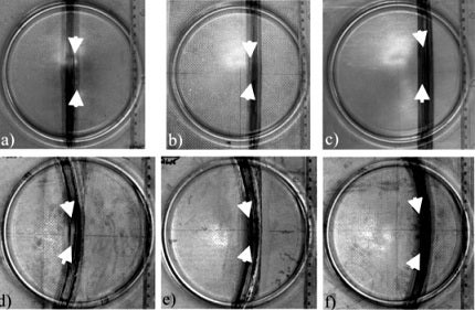
Figure 8 Stretch formed DP980 LWBs with different weld line positions and geometries (failure location is always at the soft zone i.e. sub-critical HAZ).
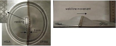
Figure 9 Biaxial stretch formed HSLA-DP980 (dissimilar combinations) LWBs prepared by diode laser welding
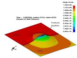
Figure 10 Predicted thickness contours by FE simulation of deformed LWBs (HSLA-DP980)