Background information
Advanced High Strength Steels (AHSS) are engineered materials that offer improved properties. High strength and good ductility (formability) are the main characteristics that make AHSS suitable for applications in auto-body construction. In-service benefits like weight reduction (gas consumption) and energy absorption (crashworthiness) are realized when employing AHSS.
Resistance spot welding (RSW) is one of the oldest processes and is the predominant method for joining steel sheets in automotive manufacturing. RSW is the preferred welding process because it is fast, easily automated, economical, clean and no additional material is required. The introduction of new and emerging grades of AHSS in auto-body construction makes RSW the favoured process for joining these steels.
The failure mode of AHSS spot weld is a complex issue due to the high alloying and the unstable phases in the microstructure. For example:
- interfacial failures are observed in dual-phase (DP) steel even at larger weld sizes
- interfacial failure can be avoided with increasing volume fraction of martensite where a reduction in hardness in the outer heat affected zone (HAZ) was detected
- martensite tempering in the sub-critical HAZ of DP steel is encountered, resulting in a localized reduction in hardness (softening)
- softened region promotes pullout failure in DP steels
- Transformation induced plasticity (TRIP) steel when is alloyed with Al failed in pull-out mode whereas Si addition leads to interfacial failure
Objectives
The broad objective of this group is to establish an understanding of the process-structure-property relationship in RSW of AHSS. Following are the important objectives:
- Analyze the fusion zone in order to establish a relationship between chemistry, microstructure and performance in AHSS spot welds
- Characterize the sub-critical HAZ microstructure to understand an important phenomenon, i.e. HAZ-softening that occurs due to tempering of martensite in DP steels
- Establish correlations between microstructure and the mechanical properties of the weld
Equipment
- Single phase alternating current spot welder
- Median frequency direct currnet (MFDC) spot welder
- Optical microscope
- Microhardness tester
- JEOL 6460 scanning electron microscope
- Instron tensile testing machine
Pictures/figures
(Further details can be found in the Publications section)
Microstructure
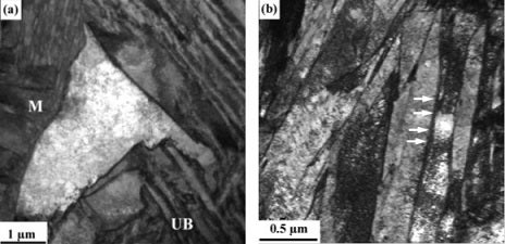
Figure 1 Fusion zone microstructure of spot welded TRIP steels (M: martensite, UB: upper bainite).
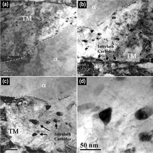
Figure 2 Typical TEM image of sub-critical HAZ (soft zone) illustrating carbides with various morphologies (TM: tempered martensite).
Hardness and lap-shear tensile testing
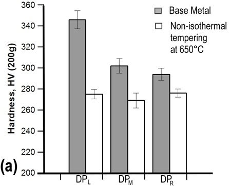
Figure 3 Effects of chemistry on softening at the sub-critical HAZ (non-isothermal tempering) in DP980 spot welds (L, M and R stand for lean, moderate and rich chemistry).
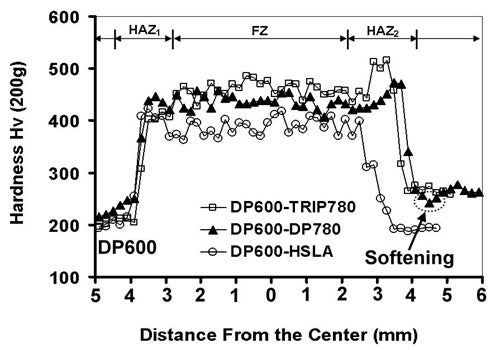
Figure 4 Hardness profiles across the weldment with dissimilar steel combinations.
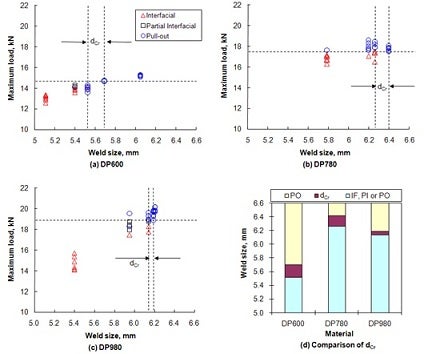
Figure 5 Maximum lap shear tensile loads versus weld size of DP steel spot welds.
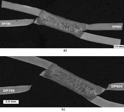
Figure 6 Cross-section of DP600-DP780 partial lap-shear tensile test at: a) just after peak load was attained; b) just after final failure.