Introduction
The advantage of hot stamping vehicle structural components is the exceptional as-formed ultimate tensile strength (1,500MPa) and the complex geometries that can be formed. The high strength of the parts is due to a fully martensitic phase transformation that occurs during the in-die quenching process. The elevated strength of the hot stamped parts allows the weight of the components to be reduced by using thinner gauge sheet metal while maintaining structural integrity and crash performance. A schematic of the hot stamping process is shown below and typically requires a boron steel blank to be austenized for approximately 5 minutes at a temperature greater than 900°C. After the soaking time, the blank is then transferred to a cooled stamping die. At the bottom of the forming press stroke, the formed part is quenched within the die. The cooling rate must be greater than ~30°C/s in order for a solid-state phase transformation (from austenite to martensite) to occur as shown by the continuous cooling transformation (CCT) diagram below.
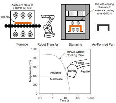
A schematic of the hot stamping process and a USIBOR® 1500P CCT diagram
In addition to the good intrusion resistance and preservation of structural integrity of hot formed parts, some components, such as a B-pillar, may benefit from regions where the mechanical properties have lower strength and improved ductility for improved energy absorption as shown in the schematic below. One method of producing a single continuous part without additional process steps is to introduce daughter phases within these regions by reducing the cooling rate within the die during the stamping operation, which in turn causes the austenite to transform into bainite, ferrite and possibly pearlite. Optimizing the hot stamping process to create a part with tailored properties is a major component of the hot stamping research program at the University of Waterloo. Equally as important is the thermomechanical processing and heat transfer characterization of this process, which is researched collaboratively with Professors Wells and Daun, respectively.

Schematic of a hot stamped B-pillar with tailored properties
When modeling (using finite elements) the crash behaviour of a hot formed structural component, the strain rate response of the as-formed material must be taken into account in order to accurately model deformation and energy absorption at the elevated rates of strain. The strain rate sensitivity of the various microstructures within the tailored part is another key focus of the research at the University of Waterloo.
Parts with Tailored Microstructures
1) Tailored In-Die Heating
At the University of Waterloo, one of the approaches taken to produce a part with tailored properties is referred to as the in-die heating process. Tooling has been developed to control the in-die cooling rate of the blank by heating and cooling specific regions of the die. Heat transfer from the blank to the tool is dependent on several factors; die surface temperature being one of the most important. As the temperature of the die is increased, the heat transfer, and thus the cooling rate, is decreased.
The a range of of tooling has been developed in-house to produce geometries that are representative of a scaled-down B-pillar and hat channel rail as shown by the CAD images below. The upper and lower dies are composed of heated and cooled sections, and are separated by a small air gap to insulate the two halves. A total of 15 cartridge heaters are used in the B-pillar die for a combined power of 8.6 kW. A feature similar to a draw-bead was introduced into the die to improve the formability of the blank without the use of a blank holder. The hat channel die has 32 700W cartridge heaters for a total power of 22.4 kW that used a binder to hold the blank symbolic of an industrial die.
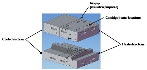
CAD image of B-pillar the hot stamping die with heated and cooled sections
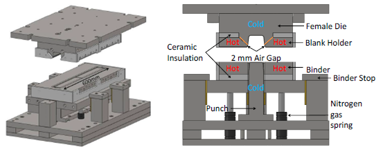
CAD image of Hat channel hot stamping die with heated and cooled sections
Two presses are for this work that are shown below. The first press shown uses a 125 ton actuator with an accumulator bank that allows for a punch speed of up to 125 mm/sec. The second has a 600 ton actuator at 38 mm/sec with 4 surrounding 60 ton kicker cylinders for fast descent (375 mm/sec) and a 300 ton blank holder with an approach of 250 mm/sec. These punch speeds are representative of industrial hot stamping processes. The furnace used for the 125 ton set up has an inner area of 600 mm x 900 mm and a 3-zone control system is installed to ensure a uniform temperature distribution which is able to heat the blanks to 950°C in less than 3 minutes. For the larger 900 ton system, the furnace used has an inner area of 1200 mm x 1550 mm and a 3-zone control system which heats the blanks to 930°C in less than 3 minutes.

125 ton hot stamping facility at the University of Waterloo
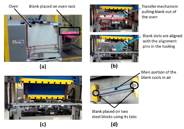
600 ton hot stamping facility showing each stage of the tailored hot stamping process (a) Blank is placed in oven (b) Blank is moved from the over to the press (c) blank is formed and quenched (d) Blank is cooled in air
Coupled thermo-mechanical FE simulations of the hot stamping process are performed using LS-Dyna as shown below for a predicted and actual hot formed part. Hot stamping material models are used to predict the decomposition of austenite to its daughter phases (martensite, bainite, ferrite and pearlite) during the hot stamping process. The accuracy of the modeling procedure must be validated against the experiments if it is to be used as a design tool in the manufacturing stage of structural components (with tailored properties) that are to be used in vehicles.
A predicted and actual hot stamped B-pillar
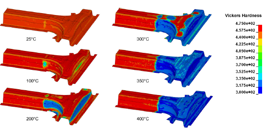
A predicted and actual hardness measurements from tailored hat channel
2) Hot Stamped Tailor-Welded Blanks
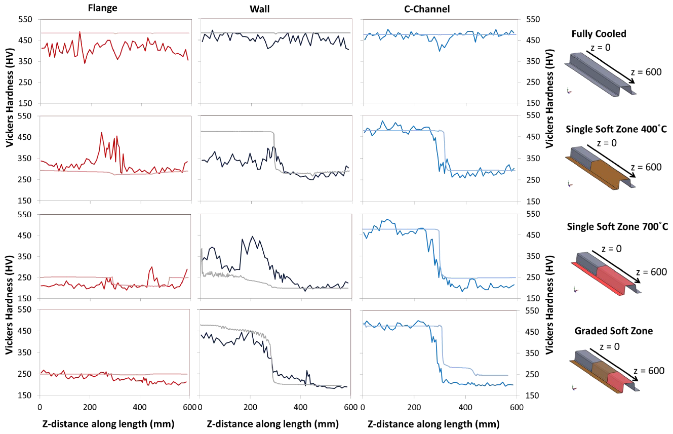
The other tailoring method studied at the University of Waterloo is the hot stamping of tailor-welded blanks (TWBs). In this method, a laser-welded blank composed of multiple alloys of the same or differing thicknesses is heated (austenized) and hot stamped between fully water-cooled dies. One of the materials is a traditional press hardening steel that achieves a strength of about 1500 MPa. The other is a material that does not harden as readily during quenching and achieves a lower strength, but higher ductility. This process uses the same presses and furnaces that are used for in-die heating. A new die with a two-piece, adjustable binder gives the flexibility to quench TWBs composed of sheets of differing thicknesses. This die has been built without cartridge heaters, allowing for more water-cooling to be used.
Die forming hot stamped tailor-welded blanks with common or different gauge thicknesses
To verify the quenching of these TWBs, hardness measurements are taken along lines extending 100 mm to either side of the weld line on the top, sidewall, and flange areas of the hat channel geometry, as shown in the figure below. The strips are sectioned and then mounted in resin pucks, which are polished for measurement of the Vickers hardness.
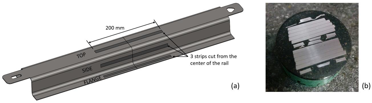
(a) Locations where specimens were cut from formed channels, (b) 200 mm long strip sectioned and mounted in a resin puck. (Ref: C. Peister IDDRG 2017)
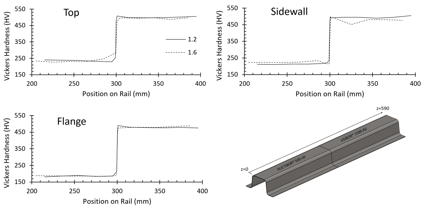
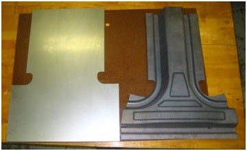
Measured hardnesses in 1.2 mm and 1.6 mm thick top hat channels formed from TWBs
The measured hardnesses show that tailored properties have been achieved using the TWBs. There is little to no effect from sheet thickness, with both the 1.2 and 1.6 mm thicknesses achieving similar hardness distributions. The size of the transition zone between the ductile material and the high strength material is very small, spanning just 2 mm in this case. These transitions are much more abrupt than in IDH parts, as thermal gradients from heated tools are not a factor here. The hard and soft zones will occur exactly where the respective materials are welded into the blank. A comparison of the transition zones in TWB and IDH parts of the same geometry is shown below.
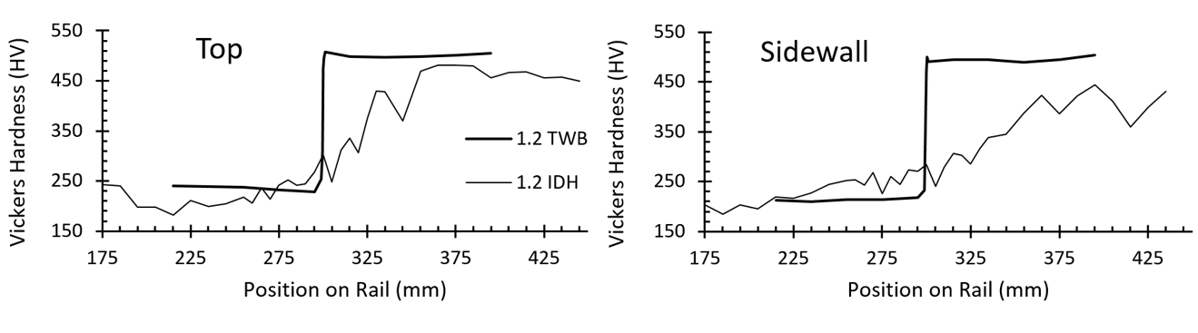
Comparison of hardness transition in top and sidewall of 1.2mm thick TWB and 700°C in-die heated tailored channels
The subsequent crash response of all of these tailored hot stamped parts is presented in the section of structural crashworthiness on this site.
High Strain Rate Characterization of Tailored Properties
Small-scale quenching experiments are conducted on blanks that are machined into miniature dogbone style specimens. These specimens are then tested in tension at low to high strain rates as discussed in the High Strain Rate Material Behaviour. The flat die apparatus used to quenched the blanks at various cooling rates below is shown below.
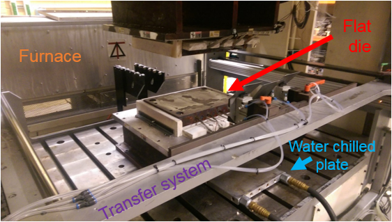
Flat die quenching apparatus
Through micro-hardness measurements and tension tests, it has been shown that the hardness vs. cooling rate follows a linear trend, as does the ultimate tensile strength (UTS) vs. cooling rate (see below). The increase in hardness and UTS are due to an increasing volume fraction of martensite in the martensite/bainite mixture (for cooling rates <30°C/s).
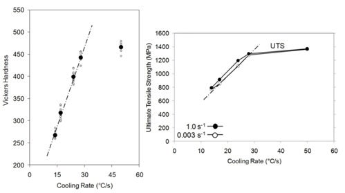
Micro-hardness and UTS as a function of cooling rate
The true stress versus effective plastic strain (or flow stress) curves generated at the various strain rates and various area fractions of martensite/bainite were used to develop a strain rate sensitive constitutive model. It was shown that a Voce hardening law with an exponential type strain rate sensitivity term accurately captured the hardening behavior and strain rate sensitive response for all of the material conditions examined in this work. The Voce parameters were calibrated for each individual material condition and mathematical functions were developed which correlated these parameters to Vickers hardness. These expressions provide the foundation of a phenomenological constitutive model referred to as the “Tailored Crash Model (TCM)”. The purpose of this model is to predict the flow stress behavior of the tailored material conditions as a function of effective plastic strain, true strain rate and Vickers hardness. A user defined constitutive model for LS-Dyna has been developed for application to crash testing of vehicle structures that have tailored properties.
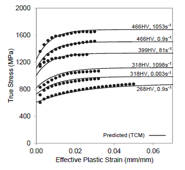
The measured (symbols) and TCM predicted (curves) flow stress curves for a variety of as-quenched Vickers hardness and strain rate values.
Gleeble Thermo-Mechanical Apparatus
A Gleeble 3500 thermo-mechanical testing system at the University of Waterloo (see below) is used to study the effect of cooling rate and plastic deformation on the tailored microstructures formed during hot stamping. The apparatus can accurately impose both a temperature and deformation vs. time boundary condition, which can be applied to match the experimental conditions. A quench head is used to impose a variety of linear and non-linear cooling rates during the simulation of the quenching process. A width gauge (C-gauge) measures the thermal expansion and dilation of the specimens due to phase transformations. The experimental results (along with hardness and metallographic analysis) are used to study the quenching process parameters and validate the hot forming FE material model.
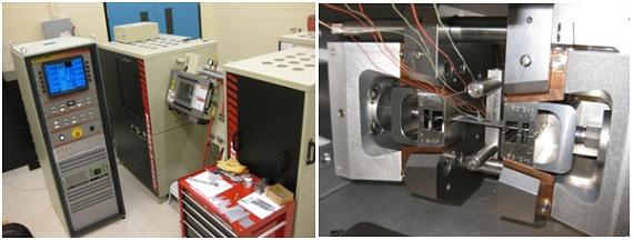
Gleeble 3500 thermo-mechanical system at the University of Waterloo
Heat Transfer Coefficients During Hot Stamping
Determining the heat transfer coefficient during hot stamping is a part of the hot stamping program at the University of Waterloo. The heat transfer coefficient is critical in determining the cooling rates that are imposed during the hot stamping of parts with tailored properties. These coefficients are an input to the hot stamping FE models and determine the accuracy of the predicted phases that form in the tailored regions. Flat die quenching experiments are conducted to characterize the dependence of pressure, temperature and surface roughness on the heat transfer coefficient. Using temperature readings from thermocouples that are embedded below the surface of the flat die (see schematic below), an inverse heat conduction method is used to infer the surface heat transfer coefficient.
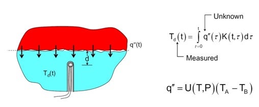
Schematic of the flat die tests used for the inverse analysis of heat transfer coefficients